


Box Build Assembly Challenges in Electro-Mechanical Integration

Article Navigation
Challenge 1: Incomplete Manufacturing Inputs and Revision Control
Challenge 2: PCBA Readiness for Product-Level Integration
Challenge 3: Cable Routing, Bend Radius, and Connector Mating Errors
Challenge 4: Mechanical Fit, Tolerance Stack-Up, and Interference
Challenge 5: Assembly Sequence and In-Process Control Gaps
Challenge 6: Test Readiness Gaps After Final Assembly
Challenge 7: Traceability, Rework Feedback, and Shipment Readiness
At REGULUS, we define box build assembly challenges in electro-mechanical integration as the risks that appear when PCBAs, cables, connectors, enclosure parts, fastening points, testing requirements, and production records do not align as one finished product. These challenges can affect assembly accuracy, product-level testing, shipment readiness, and manufacturing repeatability.
In a box build assembly project, the risk is rarely limited to one part. A PCBA may pass board-level inspection, but the finished product can still face issues if mounting holes do not align, cables are routed incorrectly, connectors are difficult to mate, internal clearance is insufficient, or test points become blocked after final assembly.
This technical guide is written for sourcing, engineering, product, and project teams that need to identify integration risks before a box build project moves into trial run or mass production. Based on our box build manufacturing experience, this article explains where electro-mechanical integration challenges commonly appear and how practical controls can improve assembly consistency, test readiness, traceability, and shipment preparation.
For a broader service overview, you can review our box build assembly services or electronics manufacturing solutions.
Challenge 1: Incomplete Manufacturing Inputs and Revision Control
REGULUS treats manufacturing inputs as the control point for defining what should be built, assembled, inspected, tested, labeled, packaged, and shipped. In box build assembly, these inputs usually include more than PCBA files. They may include BOMs, assembly drawings, mechanical drawings, cable drawings, wiring diagrams, test instructions, labeling details, packaging requirements, and revision records.
Incomplete or inconsistent inputs create production risk because the assembly team may not know which version, component, cable length, connector orientation, housing revision, label format, or packaging method is approved for production. These gaps can lead to quotation errors, material confusion, assembly mistakes, inspection disputes, and unnecessary rework.
Project-supplied items should also be controlled under the same manufacturing input review. If enclosures, accessories, labels, packaging materials, semi-finished assemblies, or custom parts are supplied by your project, their revision status, quantity, acceptance criteria, and handling requirements should be defined before they enter the assembly workflow.
Practical Control: Confirm Manufacturing Inputs Before Assembly Planning
We verify manufacturing inputs before assembly planning begins. This review reduces ambiguity before materials are purchased, work instructions are prepared, and production resources are assigned.
A controlled file review should clarify:
Approved revisions: Which BOM, drawing, firmware, label, packaging, and test document versions apply to the build.
Assembly scope: Which items are assembled, installed, connected, tested, labeled, packed, or shipped.
Project-supplied items: Which parts come from your project and which items are sourced, manufactured, or prepared by our team.
Mechanical and wiring details: Which drawings define fastening points, cable routing, connector orientation, and internal layout.
Inspection and test criteria: Which procedures and acceptance rules apply before shipment.
When your project is ready for manufacturing review, the Box Build Inquiry page can be used as a file preparation checklist for BOMs, drawings, test requirements, labeling details, and packaging information.
Challenge 2: PCBA Readiness for Product-Level Integration
REGULUS reviews PCBA readiness as a product-level integration issue, not only as a board-level manufacturing checkpoint. A completed board may still create electro-mechanical integration risk if it cannot be installed, connected, programmed, tested, or inspected after it enters the final product structure.
Board-level validation confirms the PCBA under board-level conditions. Product-level integration adds mechanical constraints, cable routing, connector mating, enclosure fit, programming access, and final test conditions. If these requirements are not reviewed early, the PCBA may create assembly risk even when the board itself is functional.
Common issues include mounting hole mismatch, connector position mismatch, board revision confusion, unclear programming status, insufficient testing connection points, and limited inspection access after installation.
Practical Control: Verify Mounting Holes, Connector Positions, Programming Method, and Test Points
Our team reviews PCBA readiness from the final product perspective. The review checks whether the board can move from board-level assembly into product-level integration without creating fit, connection, programming, or testing gaps.
The review should confirm:
Board revision: The PCBA revision matches the approved product configuration.
Mounting holes and mechanical interface: The board aligns with standoffs, brackets, enclosure features, and fastening points.
Connector orientation: Cable and module connections can be mated correctly after installation.
Programming method: Firmware or programming access is defined before the board is installed.
Testing connection points: Test points, programming ports, or fixture contact areas remain usable after integration.
Inspection access: Key areas can still be inspected after the board is installed.
If your project requires board-level manufacturing before product integration, our PCB assembly service can connect the PCBA stage with later box build assembly.
Challenge 3: Cable Routing, Bend Radius, and Connector Mating Errors
REGULUS reviews cable routing and connector mating as part of electro-mechanical integration because internal wiring must fit within limited space while maintaining correct electrical paths, connector orientation, strain relief, fastening points, and product serviceability.
A cable may pass continuity testing but still create problems during final assembly. If cable route, bend radius, label position, connector orientation, or fastening method is not controlled, the product may face wiring mistakes, assembly interference, or unstable connections.
Common errors include wrong connector mating, reversed orientation, pinout mismatch, cable connection errors, excessive bending, strained wires, missing cable labels, and routing paths that interfere with enclosures, brackets, panels, or moving parts.
Practical Control: Define Cable Routing, Pinout, Labeling, and Continuity Checks
We define cable and connector requirements before production so the assembly team can verify each connection consistently. This is especially important when your project includes multiple PCBAs, internal harnesses, user interface modules, sensors, batteries, or communication modules.
A cable control plan should clarify:
Cable start and end points: Where each wire, cable, or harness connects.
Connector orientation: How each connector should be mated and locked.
Pinout definition: Which electrical path each wire or connector position represents.
Bend radius and strain relief: How tight bends, wire tension, and connector stress should be avoided.
Routing path: Where cables should be placed inside the enclosure.
Fastening and labels: How cables are fixed, identified, and separated from interference areas.
Continuity checks: Which wiring paths require electrical verification.
These controls reduce wrong mating, pinout errors, and internal wiring mistakes during box build manufacturing.
Challenge 4: Mechanical Fit, Tolerance Stack-Up, and Interference
REGULUS treats mechanical fit as a production risk when tolerance stack-up affects clearance, fastening, alignment, enclosure integration, or connector access. In box build assembly, individual parts may meet their drawings, but accumulated variation can still create interference inside the finished product.
This challenge appears at the boundary between electronic and mechanical design. PCBAs, connectors, cables, brackets, gaskets, panels, fasteners, and enclosure parts must fit together in the correct sequence. If one interface is slightly misaligned, the issue can affect assembly speed, product appearance, testing access, or long-term reliability.
Common problems include housing fit issues, screw hole mismatch, insufficient internal clearance, connector blockage, cable compression, bracket interference, panel misalignment, gasket compression issues, and fastening points that are difficult to reach.
Practical Control: Review Clearance, Fastening, and Assembly Sequence Before Production
Our team reviews clearance, fastening methods, tolerance conditions, and assembly sequence before mass production. The review focuses on whether each board, cable, connector, fastener, housing part, gasket, and internal component can be installed without interference, compression, blocked access, or forced alignment.
A mechanical fit review should consider:
Internal clearance: Whether PCBAs, cables, connectors, modules, and brackets fit within the available enclosure space.
Fastening access: Whether screws, clips, inserts, or locking features can be reached with the required tools.
Tolerance stack-up: Whether accumulated part variation affects alignment or assembly force.
Connector clearance: Whether connectors can be mated after nearby parts are installed.
Gasket and sealing interface: Whether sealing parts are compressed evenly and do not interfere with assembly.
Assembly sequence: Whether the correct installation order prevents rework or blocked fastening points.
For products that require electro-mechanical integration, this review verifies whether electrical interfaces, mechanical structures, fastening points, and internal space constraints work together inside the finished product. If custom mechanical parts affect fit, alignment, or enclosure integration, our team can review the mechanical issue, modify the affected parts, or manufacture revised parts through services such as machining and turning, plastic injection molding, or metal fabrication, depending on the project scope.
Challenge 5: Assembly Sequence and In-Process Control Gaps
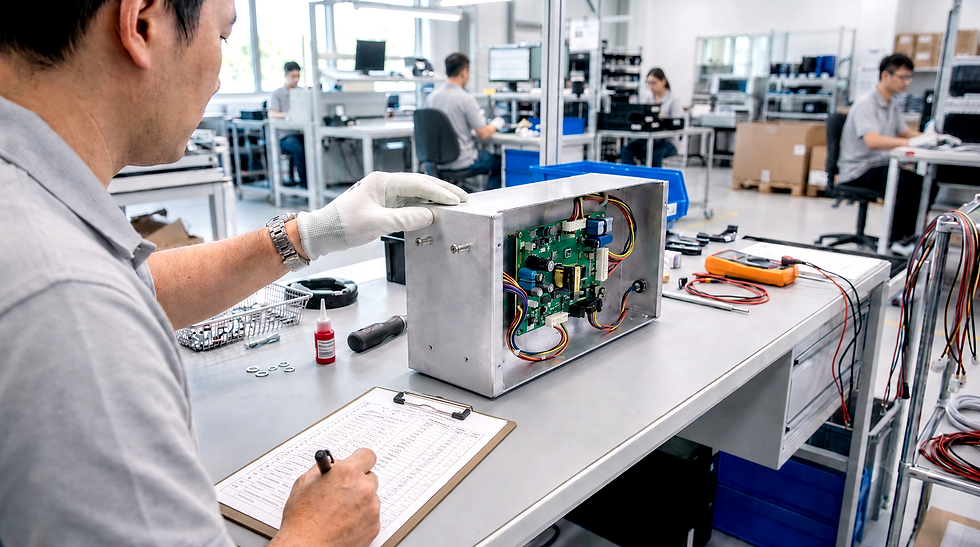
REGULUS defines assembly sequence control as a key manufacturing control when a product includes multiple PCBAs, cables, connectors, modules, fasteners, housing parts, gaskets, labels, and accessories. Even when each part is correct, the wrong assembly order can create misassembly, rework, or hidden quality risk.
This challenge becomes more visible when your project moves from engineering samples into trial run or mass production. Early samples may rely on experienced technicians, but production requires repeatable work instructions, defined checkpoints, and clear visual references.
Common problems include missed fastening steps, difficult cable placement, blocked connector locations, inconsistent operator interpretation, missing labels, incorrect accessory installation, or rework after later parts have already been assembled.
Practical Control: Build Work Instructions and In-Process Checkpoints
We build work instructions and in-process checkpoints to control assembly sequence. These instructions translate engineering intent into repeatable manufacturing steps.
Work instructions should define:
Assembly order: Which components must be installed first, next, and last.
Fastening steps: Which screws, torque settings, washers, clips, inserts, or locking features are required.
Cable placement: Where wires and harnesses should be routed before other parts are installed.
Connector mating: When each connector should be connected, checked, or locked.
Inspection timing: Which checks should happen before later parts block access.
Label placement: When serial labels, product labels, or internal labels should be applied.
Visual references: Which photos, drawings, or diagrams operators should follow.
Our Engineering and Design Solutions can cover product design, prototype build and validation, trial run, and mass production preparation. This design-to-manufacturing workflow helps refine assembly sequence, work instructions, process checkpoints, and inspection criteria before your project moves into mass production.
Challenge 6: Test Readiness Gaps After Final Assembly
REGULUS reviews test readiness before final assembly because a finished product may be physically assembled but still difficult to verify. This can happen when test points, testing connection points, fixture interface, programming method, test procedure, or pass/fail criteria are unclear before production.
This topic is different from simply listing functional testing items. Test readiness focuses on whether the product can be tested consistently after assembly, whether the test result can be judged clearly, and whether the result can be recorded for traceability.
Common issues include blocked test locations, fixture connection limitations, unclear programming status, undefined pass/fail criteria, inconsistent operator judgment, and missing retest rules. These problems can delay production because the team must stop to clarify how the product should be verified.
Practical Control: Confirm Test Points, Fixtures, Procedures, and Acceptance Criteria
We confirm test readiness before production so the product can be verified consistently after assembly. Test planning should connect electrical access, fixture interface, programming requirements, test procedure, acceptance criteria, and recordkeeping requirements.
A test readiness review should clarify:
Testing connection points: Which test points, connectors, programming ports, or fixture contact areas are required.
Fixture interface: How the product will be positioned, connected, powered, programmed, and tested.
Programming method: Which firmware, software, or configuration file applies to the build.
Test procedure: Which steps verify product-specific functions or system behavior.
Acceptance criteria: What result defines pass, fail, retest, or engineering review.
Recordkeeping: Which test results, serial numbers, revisions, or fixture IDs must be recorded.
REGULUS performs testing based on project-defined requirements and may use relevant tuning and testing equipment, documented quality procedures, or reliability testing equipment when burn-in, aging, environmental, or reliability-related checks are required by the project.
For a broader view of how inspection, functional testing, system-level verification, and traceability are managed after assembly, our Quality Control and Testing for Box Build Assembly page explains the related quality checkpoints.
Challenge 7: Traceability, Rework Feedback, and Shipment Readiness
REGULUS connects traceability, rework feedback, labeling, packaging, and shipment readiness because the finished product must be identifiable, reviewable, protected, and ready for delivery. A product may be assembled and tested correctly, but shipment-stage errors can still create quality, documentation, or delivery concerns.
Traceability shows what was built, inspected, tested, repaired, retested, packed, and shipped. In box build manufacturing, traceability may involve BOM revisions, drawing revisions, inspection records, test records, serial numbers, lot information, rework records, barcode identification, label records, packaging details, and shipment documentation.
Common problems include labeling errors, missing labels, wrong serial number labels, missing accessories, incorrect packaging materials, shipment documentation errors, weak rework feedback, and insufficient packaging protection during transportation.
Practical Control: Maintain Production Records, Final Inspection, and Corrective Action Feedback
We maintain production records, final inspection controls, and corrective action feedback throughout the manufacturing process. These controls help determine whether an issue is isolated, repeated, improving over time, or appearing in another part of the workflow.
Shipment readiness should confirm:
Final inspection: Product appearance, assembly condition, connectors, accessories, and test completion.
Label verification: Product labels, serial numbers, revision information, carton labels, and related documents.
Packaging check: Accessories, user documents, packaging materials, protective design, carton quantity, and shipment requirements.
Traceability records: BOM revision, drawing revision, test record, production record, barcode, lot, or shipment reference.
Rework feedback: Issue description, corrective action, retest status, and learning for future builds.
As an ISO 9001-certified Electronics Manufacturing Services provider, REGULUS maintains a document-driven quality assurance management system that provides traceability, inspection records, test records, production records, barcode-based identification, and corrective action feedback. Related quality practices are available on our Quality Assurance page.
Conclusion: Reducing Electro-Mechanical Integration Risk in Box Build Assembly
At REGULUS, we reduce electro-mechanical integration risk in box build assembly by controlling manufacturing inputs, PCBA readiness, cable routing, connector mating, mechanical fit, assembly sequence, test readiness, packaging requirements, and traceability records as one manufacturing workflow.
For sourcing, engineering, product, and project teams, the key is to identify integration risks before trial run or mass production. A controlled box build process should verify not only whether each part is correct, but whether the PCBA, enclosure, cables, connectors, fasteners, labels, test requirements, and production records work together as one finished product.
REGULUS is a Taiwan-based Electronics Manufacturing Services provider that offers design-to-manufacturing, PCB assembly, and box build assembly services for electronic products. Our team connects manufacturing input review, PCBA readiness, product-level integration, project-defined testing, traceability, and shipment preparation within a controlled box build workflow.
If your box build assembly project involves PCBA integration, cable routing, mechanical fit, test readiness, labeling, packaging, or traceability requirements, you can submit your project details through the Box Build Inquiry page or reach out through Contact Us to discuss your project with our team.
Comments